Software
Topics
Environment and Software Requirements
| Requirements | |
|---|---|
| Operating System | Ubuntu 16.04 |
| ROS Version | Kinetic |
| Main Languages | C/C++, Python, Shell, Arduino |
Operating System: Ubuntu 16.04 running on ARM 64-bit Architecture
To be more specific, this distro was part of the Nvidia Linux for Tegra (L4T) developer kit, which included a lot more API and drivers to harness the full power of the Nvidia Jetson CUDA cores for image processing. Furthermore, running a linux environment is very beneficial as it provides many tools for working with different type of peripherals and wireless communication. Most importantly, it fully supported the ROS development environment.
Software Framework: Robot Operating System (ROS)
Robot Operating System (ROS) is basically a huge open sourced collection of software frameworks originally developed by the Stanford Artificial Intelligence Laboratory for robotic development and research. Its main features include a centralized communication platform for passing messages between different nodes, huge library for interpreting raw data, robotic geometry library, pose estimation and SLAM, OpenCV integration, and an ever expanding network of ROS packages developed and maintain by the ROS community.
For those interested in learning more about ROS, we have developed a short presentation to get you familiar with the ROS environment and kick start your way to building your own autonomous system. The presentation link can be found here.
Main Programming Languages: C/C++, Python, Shell, Arduino
Though we developed most of our ROS packages using C/C++, the ROS environment also fully supports the development under Python. We also used Arduino in our development to allow easy raw data interpretation and leverage their robust servo control library, which in turn is C/C++ with a few minor quirks. We also had a few shell scripts which were primarily used to detect which port each of our connections were on as well as automating the launch sequence to start the autonomous driving.
Simultaneous Localization and Mapping (SLAM)
Simultaneous localization and mapping (SLAM) is the process of constructing and updating a map while keeping an understanding of where the object is at within the constructed environment. This process is very handy and is used by many autonomous system as it allows the system to get a sense of where it is in the environment. By utilizing the map generated by SLAM, we can come up with very powerful and effective path planning algorithms that can determine the best optimal route to get from one point to another point on the map. We have a more in depth introduction to SLAM which can be found here.
For much of the year, this was our plan for tackling the competition. Since we were able to perform test runs prior to the competition, our plan was to use use Hector SLAM to initially map out the course, and then running a global path finding algorithm to get our vehicle from point to point on the course.
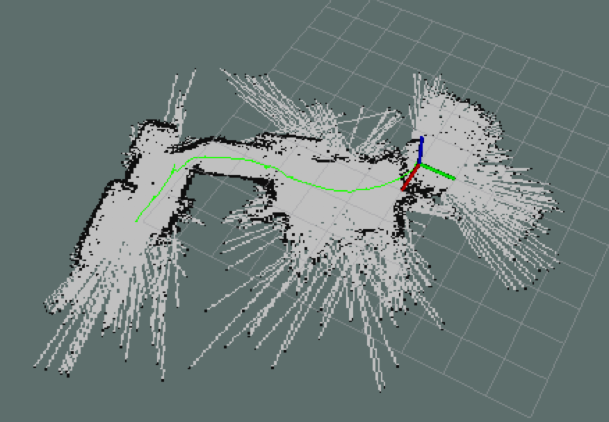
However, after much tuning, Hector SLAM never reached the reliability level we had initially hoped for. After prolong usage, our map would become distorted as shown in the above picture and this was caused by a few different factors. For one, our vehicle did not have any odometer on board. This meant that the SLAM algorithm had to detect where the vehicle had moved to relying solely on 2D LaserScan maps and IMU orientation readings. This was doable, but moving at a fast speed would result in two consecutive map frames that changed too much, causing SLAM to be confused on how far the vehicle moved. Furthermore, quick turns would also cause SLAM to be confused and generate overlapping maps. Another issue was that the ground in which the vehicle was moving on is not perfect and will have bumps. This would cause the car to wobble up and down slightly as it drives. What this meant was that the 2D plane seen by the LIDAR may also wobble by a few degrees as the car moved. This would at time put the ground in the view of the 2D plane, resulting in a map with a straight line (ground) in which the vehicle thought was a wall. The SLAM algorithm would compare this 2D map frame to the previous 2D map frame and be confused on how the wall (ground) related to the previous frame, resulting in overlapping maps. Another issue was in the SLAM algorithm itself. SLAM relied heavily on detecting certain landmarks differences between each scan to give an approximate estimation of where the car had moved to. When driving down a hallway where there were no distinct landmarks, the vehicle would not be able to distinguish how much the vehicle had moved. This meant that SLAM worked best in small confined spaces where there were a lot of obstacles to give distinct landmarks. However, the competition course was not necessarily small and had long stretches that had very little landmark. This would pose a challenge for SLAM, especially when the vehicle does not have any odometer or GPS. With that being said, the team still believe that getting a reliable map through Hector SLAM is very much indeed possible.
Nonetheless, with summer quickly coming to a close and the competition only a month away, the team came to the conclusion that it was no longer possible to get a reliable map generated by Hector SLAM ready in time. However, given the amount of hours and dedication we have already placed into this project, there was no way we were throwing in the towel after going so far. It’s time to scratch the idea of using ROS’s prebuilt SLAM/navigation packages and build our very own navigation module from the ground up!
Our Algorithm
Since we were building a general purpose autonomous obstacle avoiding race car, all we really had to do was code four dedicated modules for the vehicle that would be in charge of controlling speed, steering the car, reorienting in case of a spin out, and a main driver module that ties everything together. By the time we started implementing this algorithm, we knew a bit more about the course and were able to simplify things down a bit to our specific use case. We knew that by always picking the straight path, we would be able to complete the course. Other doubts about our sensors and specifications had been eliminated at this point, so it was time to delve into a simple, robust approach to avoiding obstacles in the form of other vehicles and randomly placed barrels.
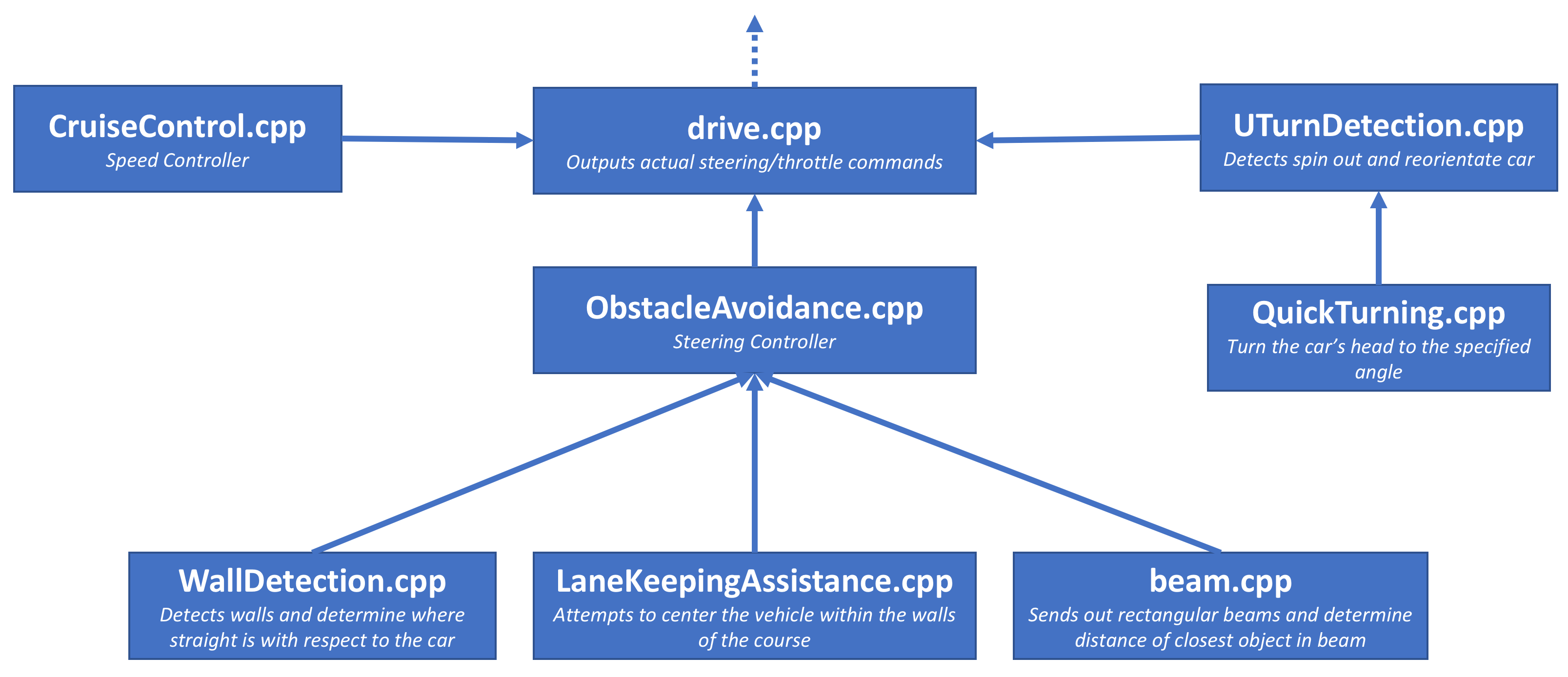
The basic hierarchical structure of our algorithm is shown above and our source code can be found on our GitHub. A more detailed description of the four main modules are described below.
Speed Controller
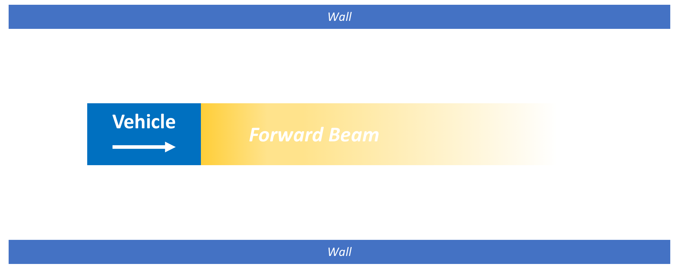
The speed controller is quite simple to implement. The algorithm projects a rectangular beam (detection area from the 2D Laser Scan), with the width matching the vehicle’s width, straight out from the front of the vehicle. It then determines the closest object to the vehicle that is within the beam’s vision. The further the object is, the faster the vehicle goes, the closer the object is, the slower it goes. For reversing, the speed controller keeps track of the same rectangular beam, but now the beam is pointing to the back of the vehicle.
Since we can control throttle by sending the ESC how many percent of max throttle, we do not have a good understanding of the vehicle’s actual speed. This meant that a throttle value will result in different real life speed based on if the vehicle is on a flat horizontal road, going up hill, or down hill. Since we did not have an odometer on board to give us the vehicle’s exact speed, we improvised by using an IMU to measure the pitch axis of the vehicle. The throttle we sent out is then scaled accordingly to take into account the additional potential energy factor.
Steering Controller (Obstacle Avoiding Mechanism)
The obstacle avoidance system is the main meaty part that makes this vehicle work. It comprises of three submodules that work intricately with each other to ensure that the vehicle is properly avoidance obstacles, while still going in the correct direction. The three submodules are (1) wall detection, (2) lane keeping assistance, and (3) beam / path decision maker.
 |
 |
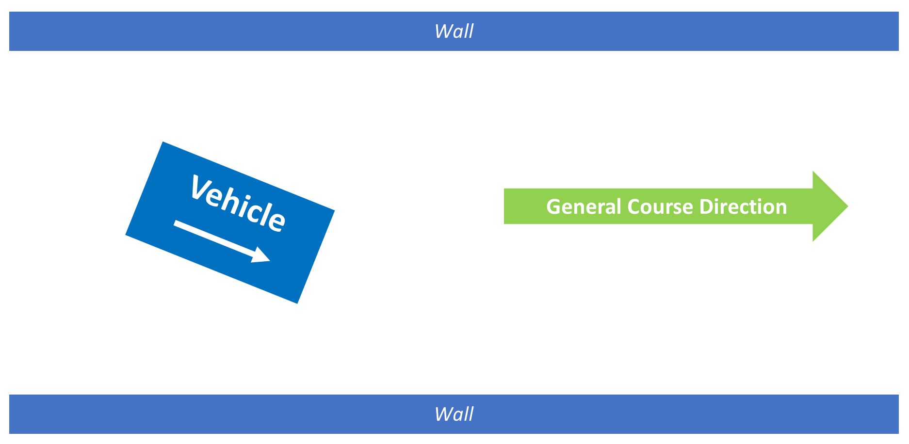
First up, the wall detection module. This module is primarily responsible for determining the general course direction. It does this by detecting walls and forming straight lines along the walls using Hough transform. By referring only to the lines that are within 90 degrees of the car’s forward orientation, we can take the average of those lines and get a sense of the course’s general forward direction.
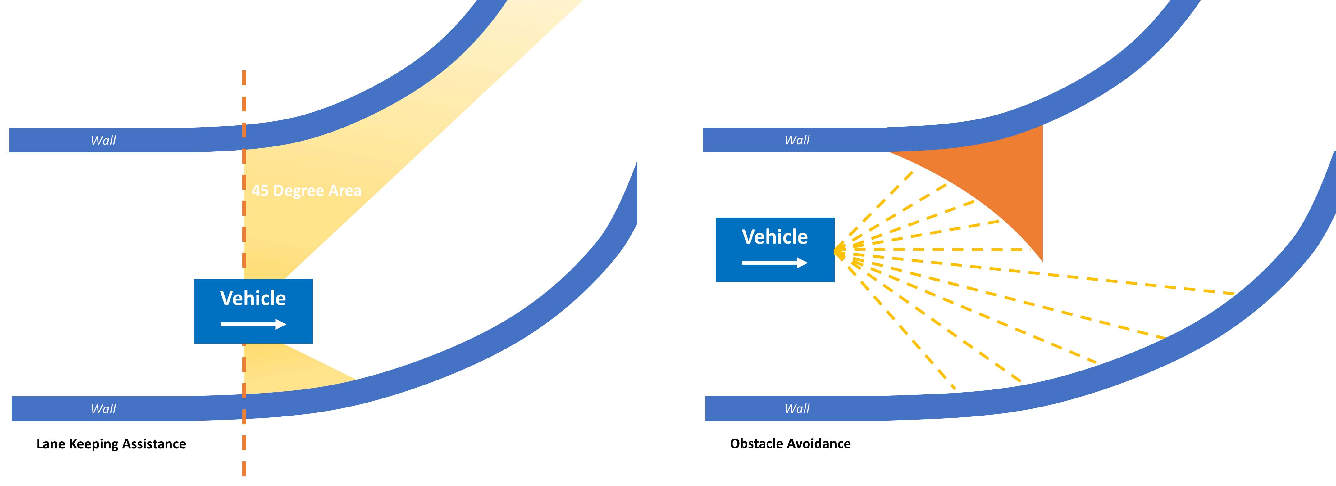
Next up, we have lane keeping assistance. This module’s primary purpose is to try and center the vehicle within the walls of the course. It does this by project a 45 degree arc from either side of the vehicle as shown from the image above. It then calculates the area within those arc. If the left area is greater than the right area, the car is staying too close to the right side and should go a little to the left, and vice versa. Though this algorithm can keep the vehicle in the course and turn the vehicle accordingly if the course is curving, it will not perform well if there are obstacles on the course. Therefore, this algorithm is used more as a helper function to provide guidance information to the main driver module.
Finally, we have the obstacle avoidance algorithm. This algorithm uses a greedy approach and basically sends out multiple beams in the 180 degree arc centered around the general course direction (calculated by the wall detection module). It then finds the beam with the obstacle that is furthest away from the vehicle and chooses that as the path the vehicle should take.
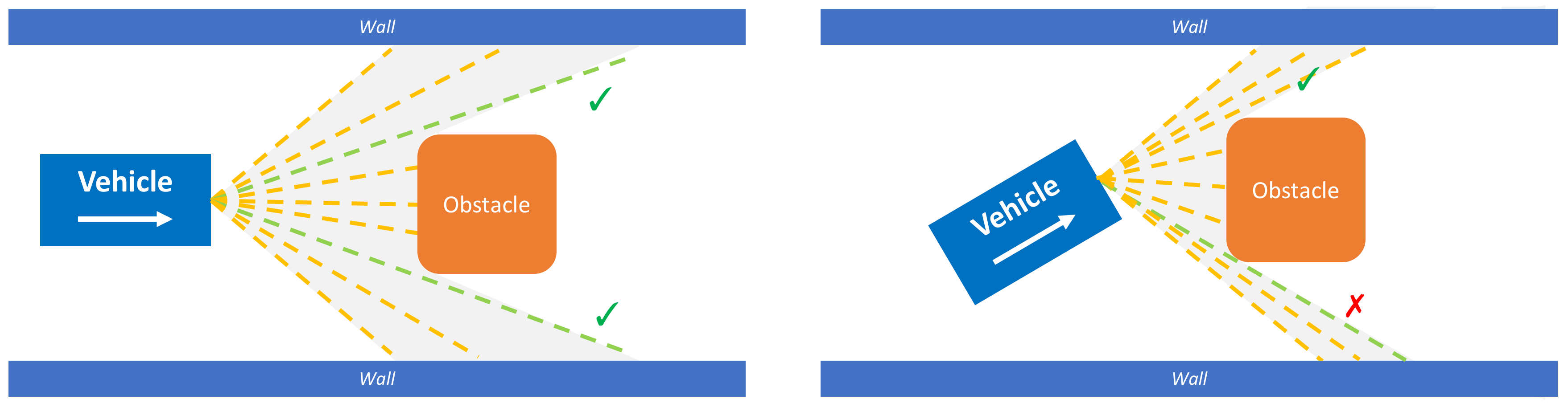
This works great, except when the vehicle is approaching an obstacle that is right in front of it as described by the image above. The vehicle sees that there are two paths which are both ideal. It will choose a path randomly, say the upper path. However, notice that once the vehicle starts turning up, it now sees that the bottom path is better. It could then change its course and go for the bottom path, but then it’ll start to see the top one is a better choice again. The vehicle will be stuck in this loop and will end up never deciding on an ideal path. What it needs is some way to remember which path it chose and then stick with it.
Therefore, our obstacle avoidance algorithm uses a scoring approach. Each path is given a score and the algorithm will choose the path with the highest score. The scoring algorithm will take into account which path has obstacles that are furthest away, but also gives bonuses to paths which are closer to the general course direction angle and the vehicle’s current forward direction. Using this mechanism, the vehicle will always strive to go towards the course general direction while also being able to definitely make up its mind about which is the ideal path to take when given an obstacle.
Crash / Spin Out Detection
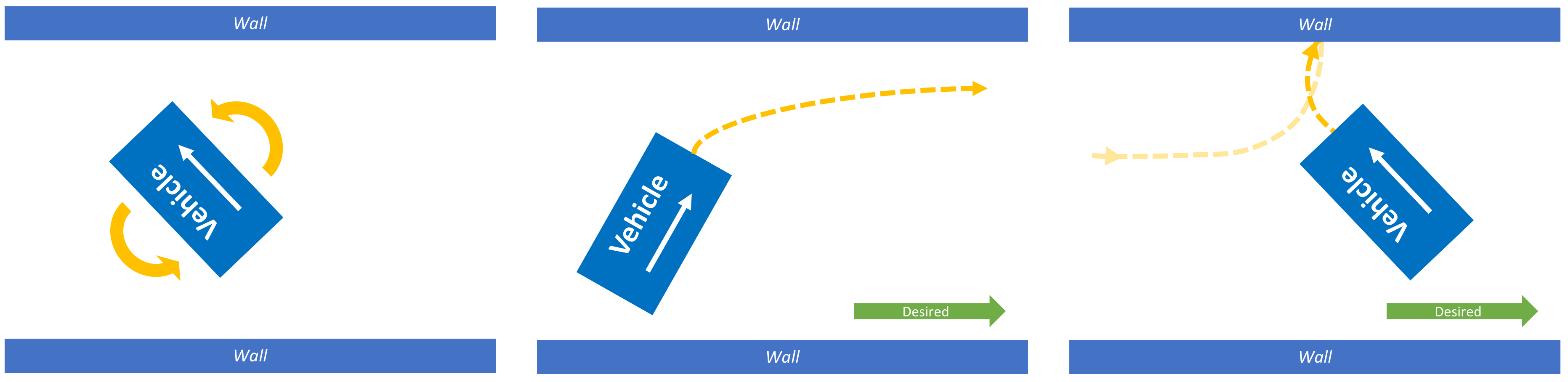
The spin out detection module has one primary task, ensuring that the vehicle is going in the correct direction. It does this by checking how far of the car’s orientation is from the general course direction. It also logs a history of the car’s previous orientation values collected by the IMU. When the module detected that the car had made a U-Turn, it will notify the main driver and then attempt to reorientate the vehicle towards the correct general course direction.
Main Driver
The main driver module is basically the captain of the vehicle. This module takes information from each of the three submodules listed above and makes the final call. It is in charge of switching between each of the three different modes of the car: (1) obstacle avoidance, (2) cruise, and (3) orientation correction. It is also in charge of detecting if the vehicle had reached a dead end or is too close to an obstacle and needs to back up and recalculate its path. Overall, all these different modules have unique responsibilities and provides solution for different problems, but by meticulously combining them together, they are able to form a fully functional autonomous obstacle avoiding race car.