Hardware
This page is dedicated to covering the hardware aspects of our vehicle. This ranges from the vehicle’s chassis, batteries, all the way to the various sensors we used.
Topics
- Back Story and Design Ideology
- Basic Vehicle Setup
- Sensors
- Custom Power Regulator and Circuit Breaker
- Future Design Changes
Back Story and Design Ideology
When tasked to build a vehicle that would compete in the SparkFun AVC 2017 competition a year ahead of the competition date, the team had to decide on an official objective / goal the team would strive to achieve. We knew that SparkFun hosted various annual competitions near the end of summer, one of which centered around autonomous self-driving race cars. We also had an impression of what to expect looking through past competitions rules and race course. But since SparkFun changes their competition year to year, and tend to not release the official rules/course until a few months before the actual competition, it was hard to gauge how the course would actually look until at least a few precious months had passed.
However, we did notice a growing trend on how SparkFun was changing their competition year to year. They were adding more obstacles that would not be stationary, using dirt terrains over concrete for less traction, and rewarding teams for not using GPS. Essentially, an ideal vehicle would have more autonomy, facing similar challenges and uncertainties to those of industrial self-driving cars. This was also obviously a measure to prevent teams from resorting to dead reckoning, a process of pre-recording vehicle’s movement (wheel rotations and turning angles) and then replaying it during the actual competition.
From this, we concluded that the best way to prepare ourselves for the competition was to build a general purpose, fully autonomous, obstacle avoiding vehicle. This vehicle should be able to navigate and explore any given flat and confined environment under various lighting conditions while being able to detect and avoid any obstacles of varying materials and sizes along the way. The team was not aiming to build a race car, but rather a robust, general purpose, obstacle avoiding vehicle. Since we knew SparkFun’s race course (along with most other race courses) would likely be on an outdoors track with only a few paths to choose from, this design would be ideal for the competition since all the vehicle had to do was explore until it eventually reached the finish line.
Woo-Hoo! With a plan in mind and vision of what the end product should be, let’s begin the next phase of determining the necessary hardware requirements that would be needed to bring this idea into reality.
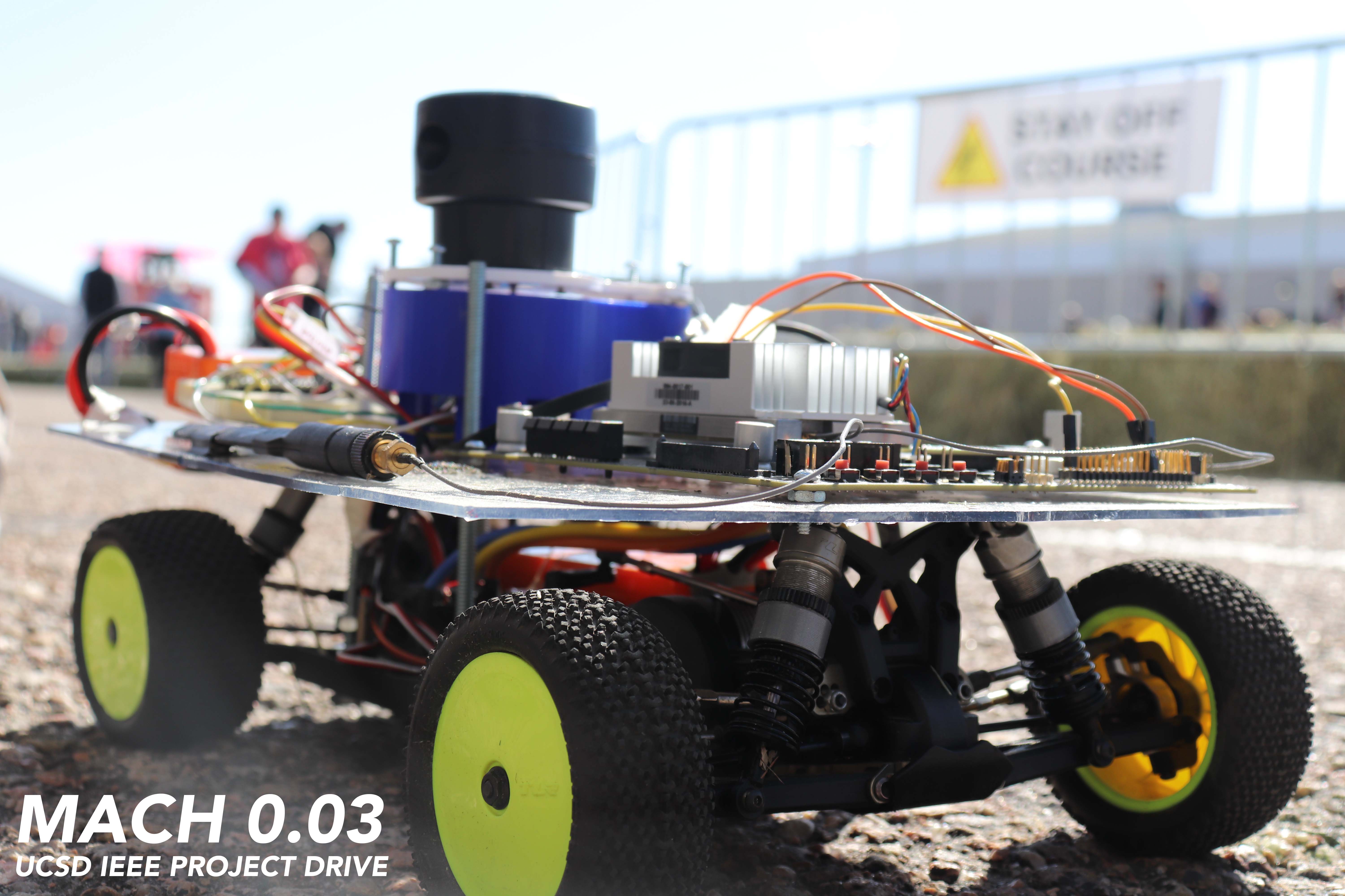
Basic Vehicle Setup
Every basic 1/10 scale race car, whether it be autonomous or remote control, are built upon four fundamental building blocks. These building blocks are (1) vehicle chassis, (2) electronic speed controller, (3) control platform, and (4) batteries. The setup we had, as well as our reasons for choosing them are listed below.
Vehicle Chassis: Traxxass
We used a Traxxass chassis passed on to us from the previous year Project Drive team. As the team was given a limited budget from our sponsors for the project, this was great as it saved us roughly $700 from buying another chassis kit and building it from scratch. The chassis definitely could have been better, since the shock absorber performed poorer than we had hoped, and the drive system was difficult to work with at the target speeds. We had custom 3D printed molds to help increase the shock absorber’s responsiveness, and compensated for some of the drive system issues through software solutions.
Electronic Speed Controller (ESC): Hobbywing Xerun SCT Pro
The ESC is also a vital part of the vehicle as it controls throttle to the actual wheel and gets the car moving. We used the Hobbywing Xerun SCT Pro, which was also passed on from the previous year, as our ESC. The great thing about this ESC was that it could be powered by any 2-4S LiPo battery. Also, a thing to note with this ESC was that when outputting PWM commands, the speed changed in a rather exponential fashion, rather than linear. This could have been a result of both the ESC combined with the chassis though. We did not use any odometers in our setup due to possible slipping errors, although if future teams have time, we highly encourage adding one to get more data to work with on actual movement, which can be fused with readings from an IMU to reduce slipping errors. One could potentially use this to implement a closed-loop system. An odometer would also significantly increase the reliability of any spatial mapping and localization (SLAM) algorithm. For those interested in controlling their ESC in the ROS environment, we have developed a ROS Arduino module that can subscribe to Ackermann ROS messages and output the appropriate PWM commands to the ESC here. This controls the vehicle as if it was like a real car, rather than many other modules which assume the vehicle is capable of turning on a dime.
Control Platform: Nvidia Jetson TX1 and Arduino Nano
The control platform is very much what gives the vehicle life. It allows the vehicle’s software to interface with much of the hardware connected to the vehicle. We chose the Nvidia Jetson TX1 as our main computing unit as it was an excellent board capable of doing everything we deemed necessary (and much more), while at the same time, running on the linux environment. This would allow us to communicate to our vehicle wirelessly through SSH, as well as visualize OpenGL applications (e.g. RViz), through services such as VNC server. Furthermore, it supported the full ROS platform in which we would be using to build our application upon. We also used the Arduino Nano as it was also compatible with ROS while allowing a quick and easy way to send out servo commands and interpret raw sensor data from our custom 360 LIDAR setup.
Batteries: Two EcoPower LiPo Batteries
No vehicle would be complete without some way of powering it! As we would be developing and testing directly on the vehicle, we needed some way to power the system for an extended period of time, while allowing our vehicle to move around freely. Furthermore, it was important to place the computer on a separate power source from the motors. We used one EcoPower “Electron” 2S Li-Poly 30C hard case battery pack to power the ESC and motors. We then used another EcoPower “Electron” 4S Li-Poly 35C hard case battery pack to power the on-board control platform and sensors. With our set up, the 2S LiPo battery would last roughly two hours of continuous driving while the 4s LiPo battery could power the Nvidia Jetson and all the sensors for roughly four hours.
Sensors
Sensors are the key element to any autonomous system. They allow the system to interpret and understand the environment around it, and therefore enable it to respond in an appropriate manner.
Since we were building a general purpose, obstacle avoiding race car that would be navigating in a flat environment, all we really needed to accomplish this was a 2D map of the car’s environment. Being on a budget, what would be more cost efficient while providing all this valuable information than a 2D, 360 degree, depth sensor! The sensors we used are listed below.
360 LIDAR: Custom Build [NOT USED IN FINAL PRODUCT]
Initially, the team wanted to build most of the hardware from scratch to learn more about how each sensor and component worked. We ended up building our custom 360 LIDAR sensors from scratch for most of the year, as described in the timeline, and it did fulfill our desires. We learned a ton on the inner workings of the sensors. We had a much clearer picture on the challenges of signal processing, how to reduce noise, and how there were many factors that affected the performance of the sensors. We actually discovered some limitations of the 2D sensor that we were using through this process, which was critical to our decision to switch sensors later on.
To give a brief overview, we used the TeraRanger One, a pseudo 1D LIDAR sensor, to retrieve range readings. We then attached the sensor on a 3D printed spinning disk that had tick marks underneath. We used a photosensor on those tick marks to get an understanding of which angle the sensor was facing. We then tweaked the TeraRanger’s ROS source code to fit our needs, and used this setup to generate a 2D map of its surrounding, which we then outputted as a ROS LaserScan Message. The Arduino code to determine angle from the photosensor can be found here, while the code that subscribed to the angles and range readings to then output a 2D LaserScan map message can be found here.
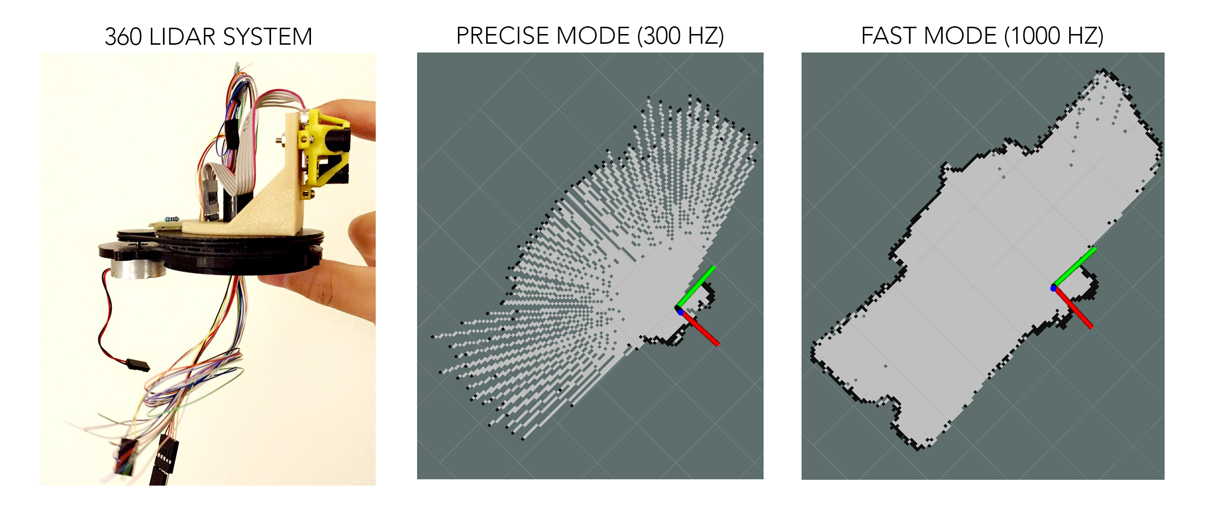
This worked! Or.. ehh.. it worked only indoor. We made one fatal mistake when building our custom 360 LIDAR. We knew we needed a LIDAR because it has been proven to work well in various lighting condition and could detect various material type. We also needed one with a very fast refresh rate as it was critical in generating a clear and dense 2D map when spinning the sensor at a high rate. The TeraRanger One’s specification on its website matched both of these conditions, and even had two versions, one which was recommended better for outdoor usage. We decided to go for it, however, we later discovered that its usage of infrared as its LIDAR sensor had very poor performance outdoor. This discovery came when we finally had a reliable working indoor custom 360 LIDAR setup at the end of spring quarter. With summer approaching and most of the team going separate ways for internships, it was not feasible for us to develop a brand new custom 360 LIDAR setup from scratch in time for the competition. Therefore, we ended up using a new off-the-self 360 LIDAR sensor as described below.
We were sad to see that our year’s worth of tuning and perfecting our custom 360 LIDAR setup did not make to the final version of the car. However, we were very grateful to have the opportunity to undergo such a task. The sensor does work very well indoors, outputting very precise and reliable 2D maps at a rate of five scans per second (limited by motor choice). But as with any engineering feat, we do not always stumble upon great innovation on our first attempt. Failure is one of the many keys to success, and with every mistake we made, we learned great lessons that led to new and improved innovations.
360 LIDAR: Scanse Sweep
The Scanse Sweep was a brand new 2D 360 LIDAR that came out in 2017, claiming to have a detection range of 40 meters, sample rate of 1000 samples/sec, and a rotational frequency of up to 10 Hz for only $349.00. The specification was great, matching what we were looking for as described in our custom 360 LIDAR setup, and the price were very competitive compared to what other companies were offering for the same price. From our experience, this sensor worked phenomenally both indoor and outdoor with very accurate map reading, whether we were spinning the sensor at 1 Hz or 10 Hz. Expect range to not actually be 40 meters outdoor, closer to 20 meters, but that was much more than what we needed for the competition. We did noticed that since our vehicle vibrated quite a bit, prolong usage of the sensor would result in slightly fuzzier map. However, stopping and restarting the sensor would recalibrate the sensor and the map would be back to normal. We would highly recommend this sensor for future teams looking for a good 2D 360 LIDAR sensor that can operate well in various environment.
Note: The Scanse Sweep requires that we manually open a serial port connection with ROS before we can actually receive any data from it when running on the Nvidia Jetson. If you are having problems reading in data using the default ROS package developed by the manufacturer, we have developed a ROS node which you can use to establish and maintain a serial connection with the Scanse Sweep which can be found here. Just run this node before attempting to read in any data.
IMU: Adafruit BNO055
Inertial measurement units (IMU) are often found on various autonomous system as it allowed the system to determine the precise orientation it is in. We initially didn’t plan on using an IMU as a 360 LIDAR would be enough to allow us to navigate and avoid obstacles. However, we added an IMU for redundancy in case our algorithm failed to detect that our vehicle has turned 180 degree and is now going the wrong way. Though this was the primary intention of using the IMU, it proved to be much more helpful at the actual competition. As we found out at the competition that the course was not all flat as it had stated in the course description. It included ramps, which would for one be higher than our 360 LIDAR 2D plane causing our vehicle to think it’s a wall, and two, cause our open loop throttle control to not detect an upward ramp and increase throttle power. Overall, we believe that using an IMU is an essential element to any autonomous system as it allows for redundancy and improved interpretation of the system’s position/orientation in respect to its surrounding environment.
Custom Power Regulator and Circuit Breaker
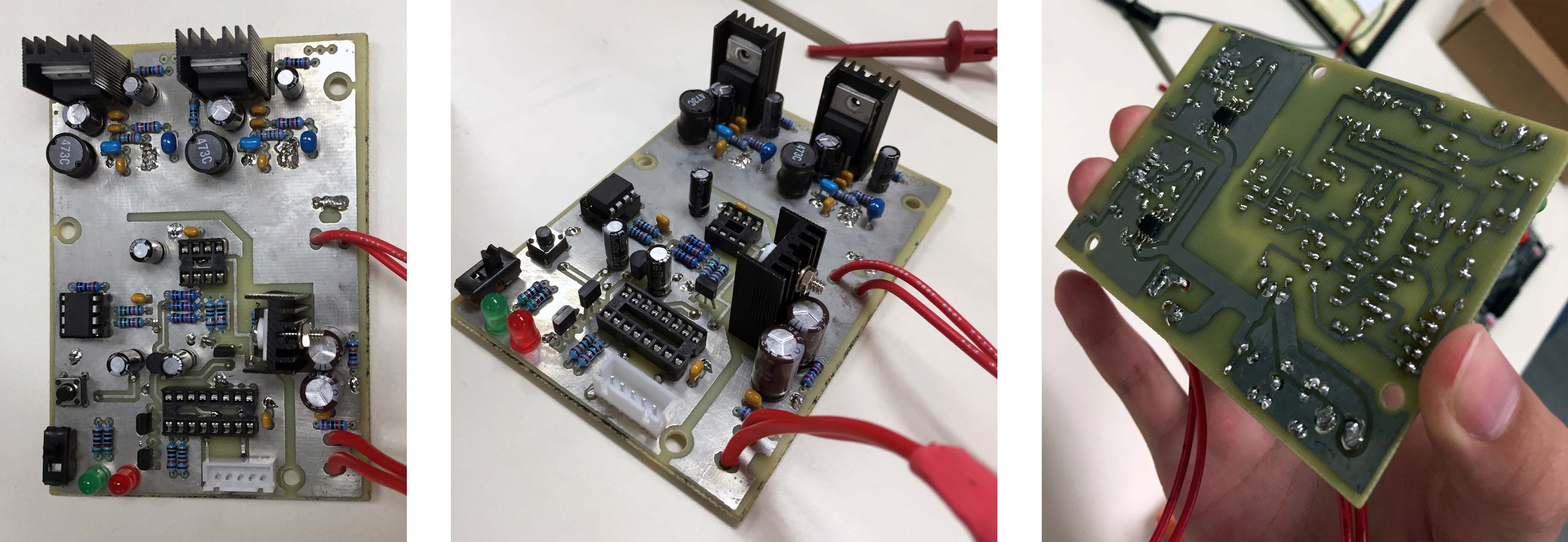
When designing our custom power regulator, we wanted it to satisfy two conditions. Since we were powering our setup using LiPo batteries, we (1) needed some way to ensure that the batteries were always operating at the ideal capacity and would never discharge too low as it would wreck havoc on the battery. We also (2) needed a constant 12V output to power both the Nvidia Jetson and all the additional sensors.
Therefore, we designed and built our very own power regulator and circuit breaker from the ground up to meet our needs. This custom PCB would receive power from the 4S LiPo battery and constantly monitor the remaining juice in it. It would output a steady 12V to be used by the control platform and sensors, and have a power kill switch which would activate once the battery reaches too low a discharge. There were two LEDs on the board, indicating green if the battery is in a good state, and red when the battery is nearing its cut off state, or has exceeded its cut off state.
Future Design Changes
For future design changes, please refer to our reflection page.